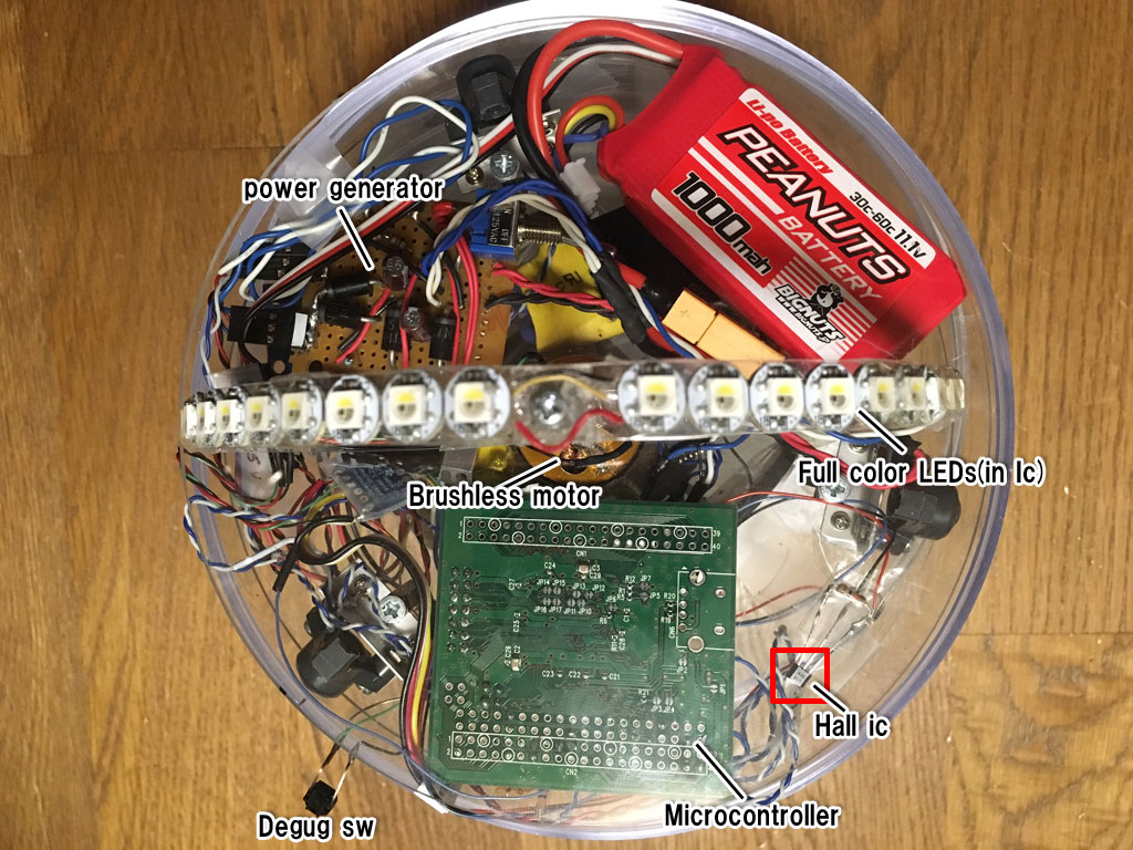
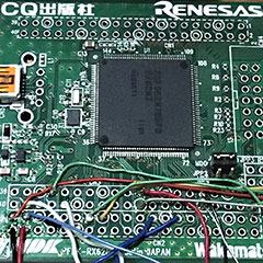
◇Microcontroller
It use RX 621 of microcomputer Renesas.
When optimization is put in, it has about processing capacity of SH2. (About half of Sega Saturn)
Since processing of about 1usec is required for motor control and LED processing,
An fast microcomputer is necessary.
マイコンです。ルネサスのRX621を使用しています。(CLOCK 96Mhz ROM 320kb)、
最適化を入れると、SH2程の処理能力があります。(セガサターンの半分程度)
モーター制御と、LEDの処理で1μsec程度の処理が必要なため、
そこそこ早いマイコンが必要でした。
選定した理由は「たまたま家にちょうどいい基板があったから」という…
◇Hall ic
In order to measure the timing of LED update, the rotation speed is counted.
ホールセンサICです。回転数を測定するもので、LEDの更新タイミングを測っています。
◇Full color LEDs
It is WS 2812 compatible IC. 24-bit coloring is possible with 1 wire serial communication.
However, although it is 24 bit in the data sheet, it did not move unless data of 32 bits was transmitted. why?
By sifting the height of the LED on the front and back, we fill the gap of LED display.
The demo title is this control cycle interval.
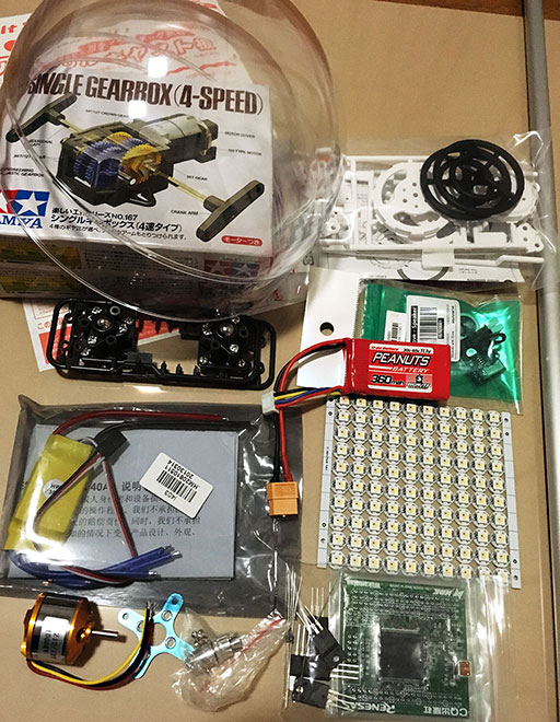
◇Brushless motor
a2212/13t 1000kv used. It is drone motor.
When turning at full speed, parts will be scattered and it will be disastrous,
so we will turn it with less than 10% output.
It sends and controls the PWM signal to the motor controller called ESC.
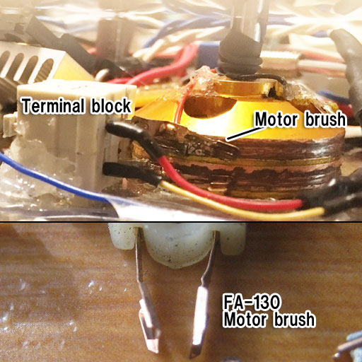
◇Terminal block
It is a terminal block. fix the brush and wire it. Fastening is screw and hot bond.
端子台です。ブラシの固定と、配線をしています。固定はネジ止めとホットボンド。
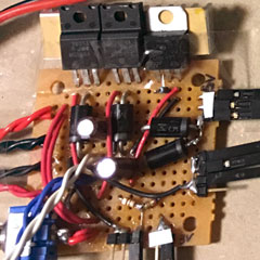
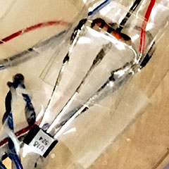
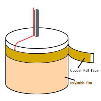
◇On the joining of rotating parts
Since the LEDs are lit while rotating, "wiring that connects even if they rotate" is necessary.
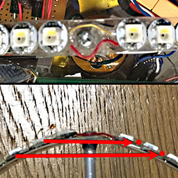
Copper tape is wrapped around the motor,
and a brush of a brush motor is applied to convey electric signals.
The brush removed from FA-130 motor.
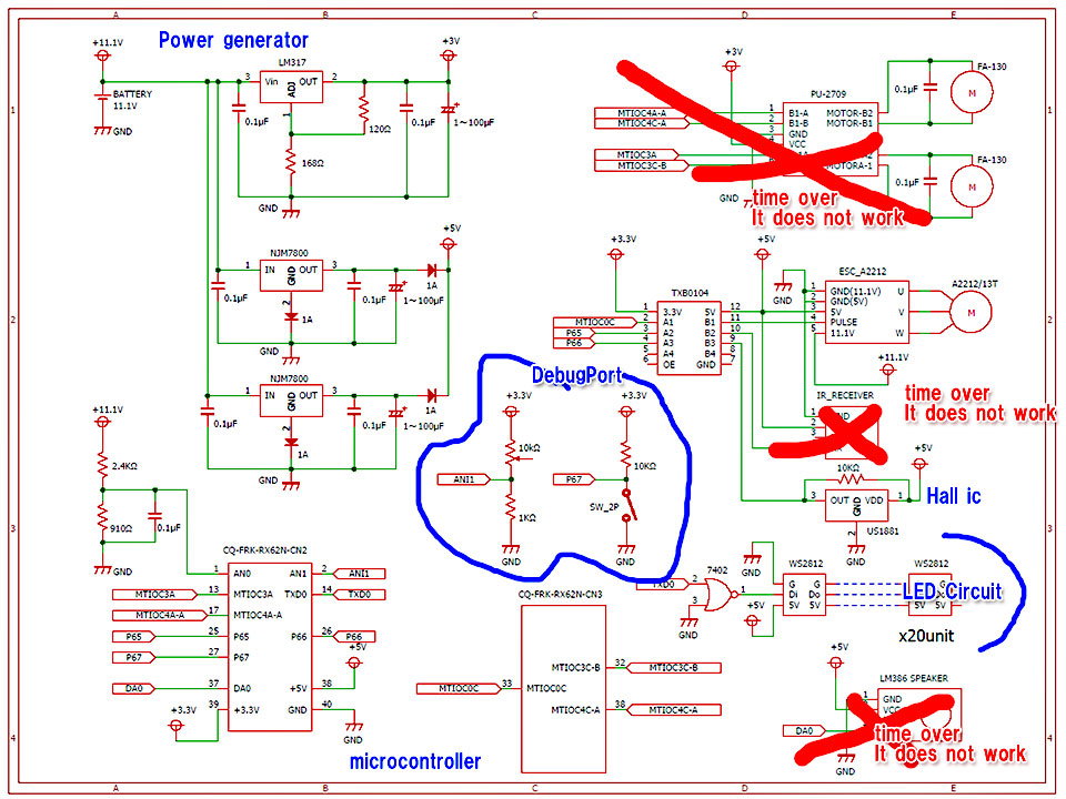
It is a circuit diagram.
Circuits were made, but there are some things that do not work due to lack of time or adjustment.
move function is gave up because power distribution adjustment and implementation did not make it in time.
Infrared control also abandoned it because I could not secure the time to make a signal analyzer.
Speqakers (probably causing power shortage) was also without being able to put in the function.
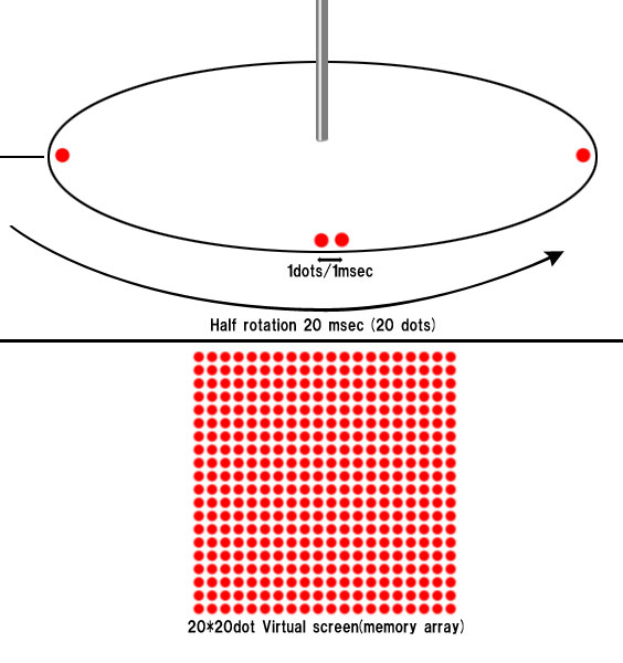
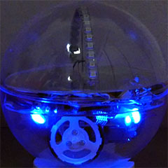
This express pixels by turning LEDs while blinking.
One pixel is illuminated for 1 msec and blinks for 40 msec in one rotation and 20 msec (20 pixels) in half rotation.
There is a virtual screen of 20 * 20 dots in the memory of the program.
After drawing it there, this hand the processing to LED control. Imqages can also be displayed.
◇Parts explanation
CQ-FRK-RX62N: RX 621 microcomputer
WS 2812: LED
LM317, NJM7800: 3 terminal regulator
TXB 0104: Bidirectional level shifter
US 1881: Hall sensor IC
ESC_A 2212: Brushless motor controller
7402: General NOT circuit
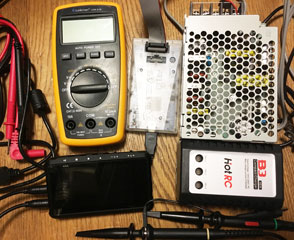
◇測定器など
Multimeter:LDM81B
Oscilloscope:DS203
Power supply:PBA/PBW50F
Chip Debugger:E2 lite
Charger:B3 PRO 2S-3S
Other:many ic datasheet
その他:データシート沢山
Most parts are available at Amazon.
The microcomputer be available in "Akizuki denshi".
in the spherical case it bought a 170 mm ball with the mail order of "Tokyu Hands".
all dimensions are designed based on it.
◇secen0
This is the time for evacuation from installation to startup.
The LED flashes in a sense of 0.5 seconds.
Music is made at 144 bps...oh! but I noticed now that it is not synchronized with music.
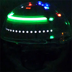
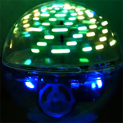
◇scene1
It is a simple effect that just lights up from the bottom.
the place which is shining other than green is a phenomenon that occurs due to motor noise on the Serial line.
this white part is one that the data did not reach the last LED and was not updated due to noise.
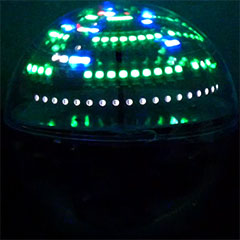
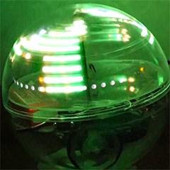
◇scene2
LEDs are lit sequentially from top to bottom, and stacked.
If you continue to send the lighting pattern all the time, the noise will be canceled and the appearance will be better.
◇scene3
this opened 2 dots and scrolled from bottom to top, but it was not very beautiful.
so, it switches to the next scene in a short number of seconds.
◇scene4
It is change the color in the HSV color space while lighting all.
Perhaps it is a place where this scene takes a picture and it looks good.
It has a lot of light intensity, it glows beautifully.
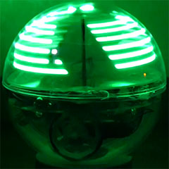
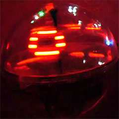
◇scene6
The ascii of "TOKYO TDF 2017" are switched and displayed.
It is difficult to capture with cameras, but it is distinguished by eye.
It think would have been more difficult for they to take pictures ...
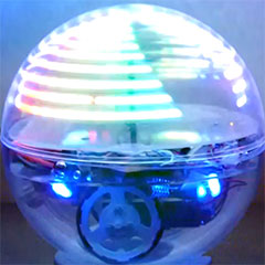
◇scene7
This is "katakana" 「イ」
At first, I tried to display the northern hemisphere of the globe, but I abandoned it because the resolution was low.
「イ」 is the shape that is most easily recognized in shape. which was used for Japan's first TV transmission test.
Besides this, classic fire effect and 3D figure of wire frame etc.
I was trying to display, but I am abandoning the adjustment due to time.
While finding time, I am thinking to add patterns when I make new videos.